Archive
Making Waves VHF and up….
Upon moving to the new QTH in February this year (2018), I decided that I was going to spend more time operating on VHF, UHF and above. Sure enough, I got my trusty FT-480R set up on the bench and fitted the 2m 10element Yagi to the wall at the end of the house with a short Yagi for 70cm above it (and rotator below). The added bonus of being 154m ASL was also something I planned to take advantage of.


I also had my FT-817 connected for UHF (70cm) and a transverter for 23cm.
 Transverter
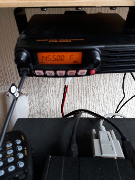
For 145MHz FM I bought a new FTM-320D (Yaesu) which I plugged into my Diamond X-50 colinear.
Meanwhile, I had been monitoring the local repeaters on my handheld radios – Alinco DJ-G7 and Yaesu FT-252 from inside the shack, so I knew my coverage was much better than at the previous QTH. I could now hear GB3LM, GB3NF and GB3CF at fully quieting. Yes, I know repeaters aren’t DX but they are a good way to evaluate your coverage.
On 2m FM I had many a QSO with local operators as there seemed to be much more activity on 2m locally than there was at the previous place. This was certainly encouraging. The XYL and I had also discovered a high point that was easily accessible – the Kirkby Summit Tip – at 193mASL, so one sunny(ish) day in May I went up witht he handheld. Just using the supplied rubber duck I called CQ /P and received a reply rather quickly from an amateur in Huthwaite (a village on a hill). We ended up with several other amateurs joining in, some very local and some a little further afield.
It was in May that I started concentrating more on J3E (SSB) on 144MHz, I took part in the UKAC contest on the 1st – just for an hour – and logged 9 QSOs in both the IO93 and IO92 squares – not too bad with 10W. Then on the 7th I managed to work a G1UUO/P who was on a SOTA activation. Conditions were generally lifting with the weather improving now. On the 13th I worked GB5HW – a windmills on the air SE station from Derbyshire. On the 20th I had another good day with 5 in the lag from IO93, IO91 and IO81 squares.
Come June we had a combination of high atmospheric pressure and early morning mist. This gave rise to excellent tropospheric ducting conditions and I managed to work GW1YBB (Wales) in IO81 and PE1BEW (Netherlands) in JO32. At the beginning of July was the RSGB VHF/UHF Field Day, so I switched the radios on and worked into Scotland, Wales, Eire and most of England over two days on 2m. I have been rather pleased with my 2m activity thus far. I have now also added a 144MHz PA and GAS-FET preamp to the setup to give me a whopping 45W when needed. This gives me an effective radiated power (ERP) of 357.448W with the 11.6dBi gain from the 10 element Yagi.
UHF I didn’t find very effective but this is due to a fault that has developed with the audio stages on the FT-817. Something I shall have to look at when I get the time.
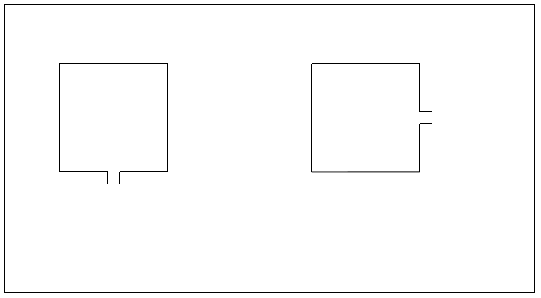
I have recently started moving towards the microwave bands. I have built a biquad or backfire array antenna for 3.4GHz (9cm) pictured below. This is to be matched to a transverter that I am hoping to acquire soon.
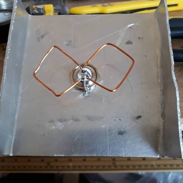
Today I took delivery of some 5.7GHz ATV equipment. It is actually a 5.8GHz FPV Transmitter, a 5.8GHz FPV receiver and a CMOS camera – the type used by radio controlled drone or aeroplane fliers to film video. The frequency of each is programmable from 5.658GHz – 5.917GHz so I shall pre-set each to 5.665GHz for the amateur radio portion of the band. I shall build a double biquad antenna for 5.7GHz (6cm) – like the above picture but with 4 Quads as opposed to 2. This will give approximately 18dBi of gain. I also hope to find a PA to increase the 600mW output to somewhere around 2.5W. Pictures are below.


More will follow on this last piece as I get the ATV system set up and operational.
Making Waves – 2m Quad
The M0CVO High Gain 4 Element Quad for 2M
The antenna I am now going to describe is one that I designed some time ago. It is a high gain quad beam for 2M (144 – 146 MHz) band. The forward gain of such an antenna is approximately 11.5 to 12dBd, that’s approximately 10.6 to 10.8 times the output power from the rear of your transmitter. For example, say you were operating a 10 Watt txr, the effective radiated power (erp) would be 10*10.6=106 Watts.
All this power and still a relatively small antenna; the boom is a mere 1 metre in length and may be constructed from 1” (2.5cm) square, weather treated, wood. The elements are constructed from 2.0mm diameter enamelled copper wire (ecw), the dimensions of which are shown in Table 2.
All the dimensions were calculated using the formulae in table 1, which was, admittedly gleaned from “The Amateur Antenna Handbook” by William I Orr, W6SAI, although the beam is of my own design.
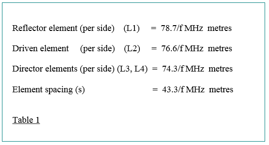
For horizontal polarisation feed from bottom for vertical polarisation rotate by 90◦
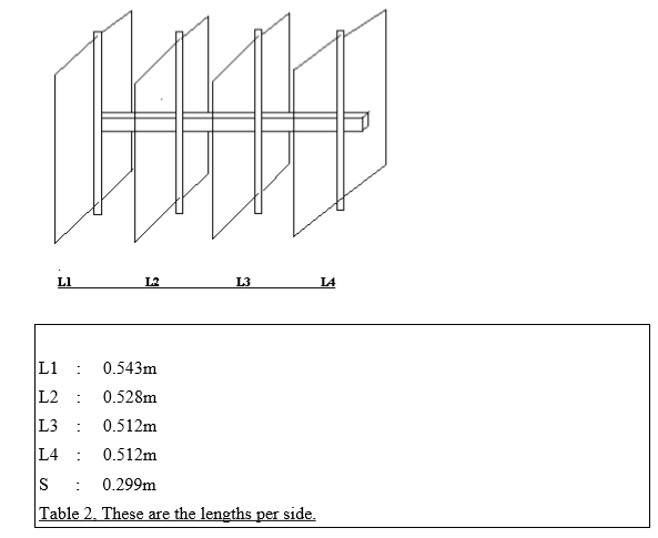
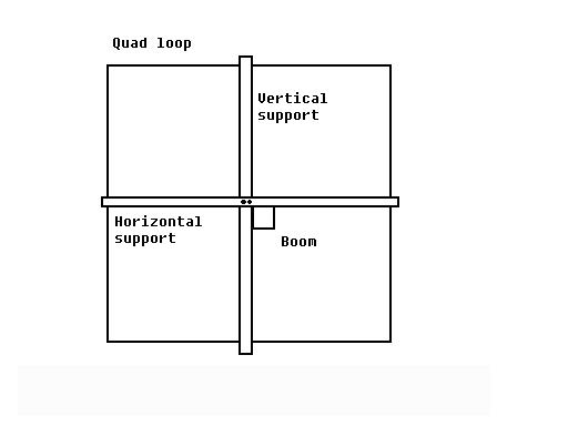
To strengthen the elements of the quad a 2nd support can be fitted which will also make it easier to attach to the boom.
Making Waves – The Shorty Forty
I was taking part in a Twitter conversation today with someone building the helical antenna published in this month’s RadCom, the RSGB member’s magazine, and having issues with the matching of it. He was trying it out due to lack of space and a poor earth (clay) at his QTH.
I set to thinking and remembered an antenna design that I used to hand out to Foundation and Intermediate Licence trainees when I was mentoring them through their studies and assessing their practical assignments. This was the Shorty Forty antenna because we don’t all have the requisite 20.28m of free space to string a dipole across. I shared the plans with him and later thought “Why not share them for everyone?” so here goes:
The Shorty 40 – Helical Whip for 7MHz
So you want to get onto 40m but don’t have room for a dipole (20.28m)? Then this could be just the answer if you have a little time on your hands and enjoy home construction.
The Shorty 40 is a helical whip for 40m wound on a 3m long, 32mm diameter piece of PVC tubing (the sort available in most DIY stores). You will need 21m of 1.2mm diameter enamelled copper wire, 80cm of 2mm diameter ECW and 10 or 15m of 1.5mm diameter insulated copper wire (the sort used for lighting circuits or earth wire). You will also need a SO239 connector and a piece of angled aluminium.
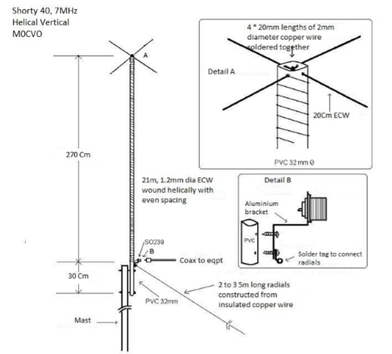
The picture says it all really but, just in case, begin by winding the 21m of copper wire along the length of the pipe, using tape or adhesive to secure it along the way. Cut the 80cm of 2mm ECW in half and push through the holes drilled in the top of the pipe. Solder together in the centre and solder the end of the coil here also. Drill a 16mm hole in the aluminium bracket for the SO239 socket and then attach it to the pipe using machine screws. Then solder the other end of the coil to the centre pin of the socket. Connect pipe to mast and connect two or three 5m radials to the solder lug on the aluminium bracket. Attach coax, raise mast and away you go.
Disclaimer I cannot claim to be the first person to develop an antenna such as this but I have researched ideas on the internet and in books on the subject – from ARRL, PW Publishing and RSGB publishing – and changed them to suit modern metric measurements and make them easier to understand and build.
Making Waves – Antenna Polarisation Issues
Someone asked me to explain why he was unable to hear some horizontally polarised stations on his vertical even though the vertical operates at 360degrees. This was the explanation I gave him:
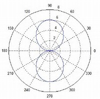 fig.1
fig.1
Fig.1 shows the radiation pattern of a 1/2 wave dipole, showing strong signals off either side with nulls towards the ends.
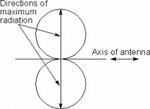 fig.2
fig.2
This is better shown in fig.2. Assuming that the antenna runs from north to south in a straight line, any station to the east or west will be able to hear / work it but if they are located north or south of it they will struggle to hear or be heard.
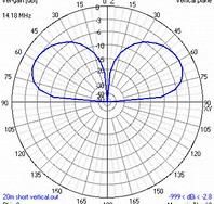 fig.3
fig.3
fig.3 shows the radiation pattern of a vertical antenna. A vertical antenna, when placed over a good earth, will radiate evenly in all directions and so can be heard/worked by any station in any direction that is either vertically or horizontally polarised. However, those who are horizontally polarised must have their antenna running in the correct direction for the reasons outlined above. There is also a 3 – 6dB loss in signal due to the change in polarisation although this effect is only true in a vacuum as scatter caused by other objects and reflection changes the polarisation of the radio waves anyway.
Making Waves, 23cm and infinity
As I have stated previously I purchased a 1296MHz transverter from SG-Lab in Bulgaria. Anyway, upon applying power to it and testing the transmit (with an IF of 145MHz at 2.5W from my FT-817) I noted that it was not working as described. Upon opening up the top of the case I noted that one of the components was raised and obviously burnt. I contacted Hristiyan, LZ5HP, at SG-Lab and sent photos of the faulty component in situ. He immediately identified it as a short in the choke having caused the problem and I returned the unit to him. Two weeks later it was back with me in full working order with a replaced choke. This time when I applied power and some IF it worked as it should.
I also mentioned that I would look at constructing a DL6WU Yagi but, unfortunately, work has got in the way and I just haven’t had the time. I looked online for suppliers and, after much deliberation, decided to purchase one from Dual Antennas in Serbia (www.antennas-amplifiers.com). This was down to both price and quality. Although there are manufacturers both in England and in Germany, Dual seemed to offer the best deal. For a 13 element Yagi it cost me 59€ plus shipping. there was the other issue that when it arrived in the UK it was held by customs for a week whilst they added import charges and VAT but that only came to £19.15.
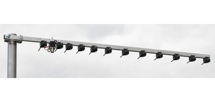 The 23cm Yagi from Dual.
So now I am fully operational on all bands from 80m – 23cm (except 4m currently). I have not yet had a QSO on 23cm although I have put out a few CQ calls, so maybe next Thursday evening during the UKAC contest.
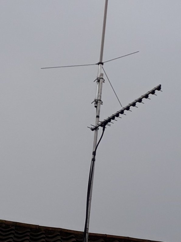
The 23cm Yagi up at CVO Towers
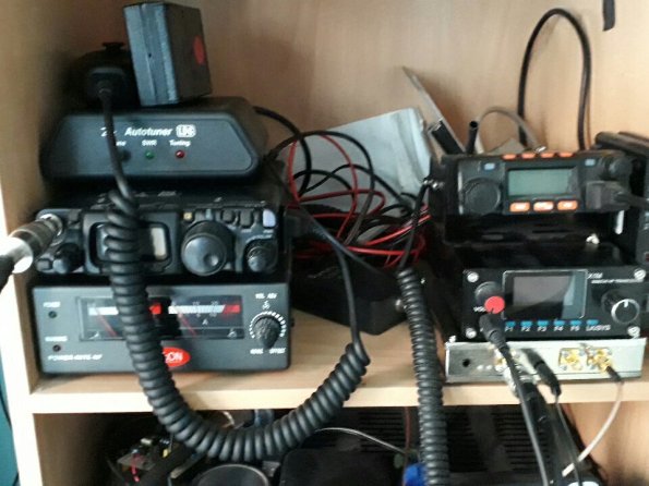
The transverter visible in operating position below the X1M HF QRP set with the FT-817 providing the IF to the left.
Making Waves – Higher Bands, Transverters and Kanga.
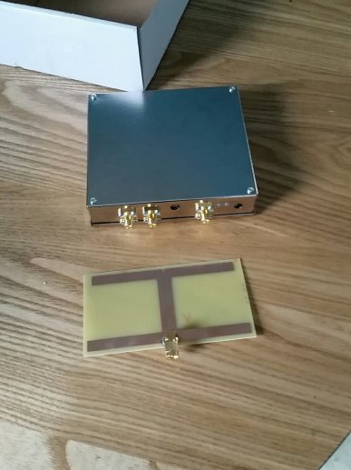
 The SG-Lab 23cm Transverter
So I finally bit the bullet and decided that it was time to extend my amateur radio boundaries beyond 433MHz. I read various reviews and product descriptions and decided on purchasing a SG Lab 1296MHz transverter. I sent an e-mail to Hristiyan, LZ5HP in Sofia Bulgaria who constructs these units enquiring about pricing. He promptly replied with a return e-mail and a PayPal invoice for 145€ (£132GBP). I paid up (cheaper than expected) and within two days had tracking details and confirmation that it was on its way. It actually arrived surprisingly quickly (about 1 week) using Bulgaria Post and then Royal Mail when it arrived on our shores.
The unit supplied is enclosed in a smart tin case and comes complete with an HB9CV “test” antenna printed on FR4 laminate. Both are shown in the picture above. There is also a DC plug (you need to supply the wire and solder this yourself) for the power. You will also need a BNC to SMA pigtail lead to connect to whatever you choose to use as an IF. I am making use of my mostly redundant FT-817 for this. The IF is from 144 -148MHz.
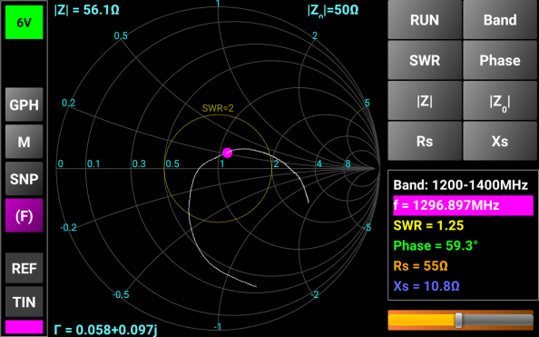
For a test antenna, the supplied HB9CV demonstrates a rather good match as can be seen from the above Smith Chart produced by my MiniVNA Tiny. With 3.2dBd gain it has quite promising performance as a suitable antenna for local ops too. The instructions are available online at http://sg-lab.com/amateur.html and these will be needed for setting up the unit. Nothing too complex though but you will need to remove the top cover and possibly use some long nose needle pliers. for setting jumpers.
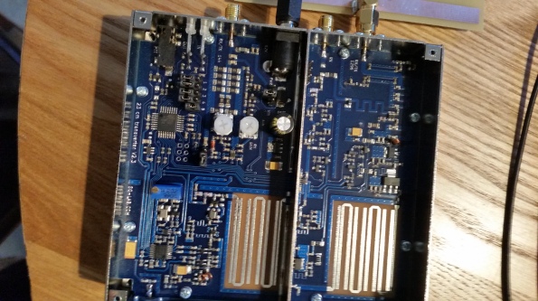
The picture above shows the transverter with the top cover off for the purpose of setting up using the jumpers. Output power (up to 2W) can also be adjusted here using the trimmer visible on the left.
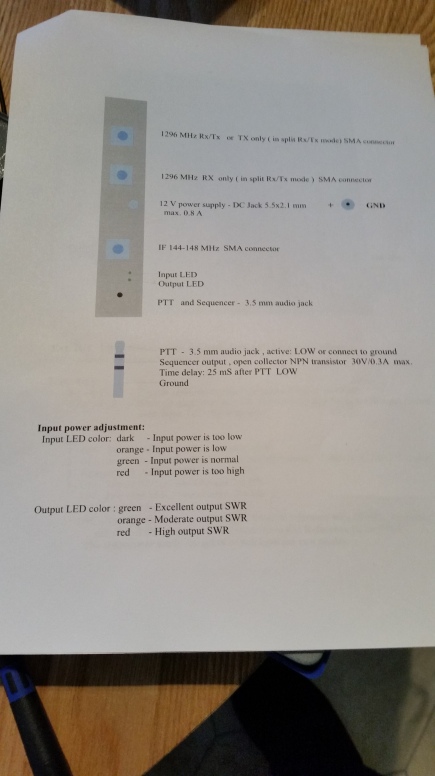 Most functions can be monitored using the LEDs at the side.
After purchasing this then discovered that the completed units are stocked in the UK by Kanga Products (www.kanga-products.co.uk) so I could have obtained it possibly faster and cheaper but we live and learn. I may look at the 13cm (2300MHz) transverter at a later date – also from SG Lab and I will look then to see if Kanga have it first.
Now I am going to build a DW6LP type Yagi Beam for 23cm so I can put the unit to full use.
Making Waves – Fundamentals of radio Antennas part 2
Standing Waves
Assume that it is possible to have a wire conductor with one end extending infinitely, with an RF transmitter connected to this wire. When the transmitter is turned on, a RF current in the form of sine waves of RF energy moves down the wire. These waves of energy are called travelling waves. the resistance of the conductor gradually diminishes the amplitude of the waves, but they continue to travel so long as the line does not come to an end.
The antenna, however, has a finite length. Therefore, the travelling waves are halted when they reach the end of the conductor. Assume that the RF transmitter is turned on just long enough for one sine wave of energy to get on the line (Fig.4A). This travelling wave is moving down the antenna toward the end. When the wave reaches the end of the conductor, the current path is broken abruptly. With the stoppage of current flow, the magnetic field collapses. A voltage is induced at the end of the conductor that causes current to flow back towards the source as in Fig.4B. The wave is reflected back to the source and , if a continual succession of waves is sent down the line, they will be reflected in the same continual pattern. The wave moving from the transmitter is known as the incident wave and its reflection is known as the reflected wave.
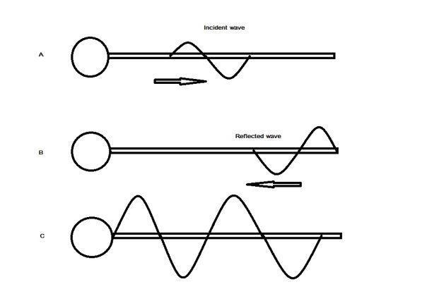
Fig.4 Travelling waves on an antenna and typical resultant wave.
A continuous flow of incident waves results in a continuous flow of reflected waves. Because there is only one conductor, the two waves must pass each other. Electrically, the only current that flows is the resultant of both of these waves. The waves can reinforce or cancel each other as they move.
When they reinforce, the resultant wave is maximum; when they cancel, the resultant wave is minimum. In a conductor with a finite length, such as an antenna, the points at which maximum and minimum occur (Fig.4C) are stationary. In other words, the maximum and minimum points stand still, although both the incident and reflected waves are moving. Because of this effect, the resultant is referred to as a standing wave.
The development of the standing wave on an antenna by actual addition of the travelling waves is illustrated in Fig.5. At the instant in A the incident and reflected waves just coincide. The result is a standing wave having twice the amplitude of either travelling wave. In B, the waves move apart in opposite directions and the amplitude of the resultant decreases but the points of maximum and minimum do not move.
When the travelling waves have moved to a position 180 degrees phase difference, the resultant is zero along the entire length of the antenna, as shown in C. At this instant there can be no current flow in the antenna. The continuing movement of the travelling waves, shown in D, builds up a resultant in the direction opposite to that in A. The in-phase condition of the travelling waves results in a standing wave, in E, equal in amplitude but 180 degrees out of phase with the standing wave in A.
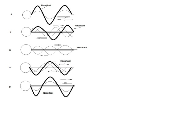
Fig.5 Development of standing wave from travelling wave.
If the progressive pictures of the standing wave are assembled on one set of axis, the result is that shown in Fig.6. the net effect of the incident and reflected waves is apparent. The curves are lettered with reference to Fig.5. As the travelling waves move past each other, the standing wave changes only its amplitude. The fixed minimum points are called nodes and the curves representing the amplitude are called loops.
The concept of the standing wave can be applied to the half wave antenna with reference to either current of voltage distribution at any instant. This application is possible because there are travelling waves of both voltage and current. Because voltage and current are out of phase on the half-wave antenna, the standing waves are also found to be out of phase.
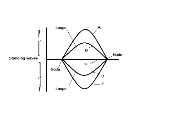
Fig.6. Standing Waves
Part 3 to follow.
NB. This collection of items was first produced as an adaption of information from a US Army training manual on antennas and radio propagation. This manual is no longer in print.
Making Waves – Fundamentals of radio Antennas part 1
The electrical and magnetic fields radiated from an antenna form the electromagnetic fields, and this field is responsible for the transmission and reception of electromagnetic energy through free space. An antenna, however, is also part of the electrical circuit of a transmitter (or receiver); and, because of its distributed constants, it acts as a circuit containing inductance, capacitance and resistance. Therefore, it can be expected to display definite voltage and current relationships in respect to a given input. A current through it produces a magnetic field and a charge on it produces an electrostatic field. Thes two fields together form the induction field.
Voltage and Electric Field
When a capacitor if connected across a source of voltage, such as a battery (fig.1), it is charged some amount, depending on the voltage and the value of capacitance. Because of the emf (electromotive force) of the battery, negative charges flow to the lower plate, leaving the upper plate positively charged. Accompanying the accumulation of charge is the building up of the electrical field. The flux lines are directed from the positive to the negative charges and at right angles to the plates.
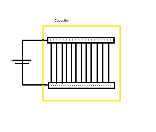 Fig.1 Charges on the plates of a capacitor.
If the two plates of the capacitor are spread farther apart, the electric field must curve to meet the plates at right angles (Fig.2). The straight lines in A become arcs at B, and approximate semi-circles in C, where the plates are in a straight line. Instead of flat metal plates, as in the capacitor, the two elements can take the form of metal rods or wires. In B the rods are approximately 30 degrees apart and the flux lines are projected radially from the positively charged wire to the negatively charged wire. In C the rods are in a straight line and and the flux lines form a pattern similar to the lines of longitude around the earth. To bring out the picture more clearly only the lines in one plane are given.
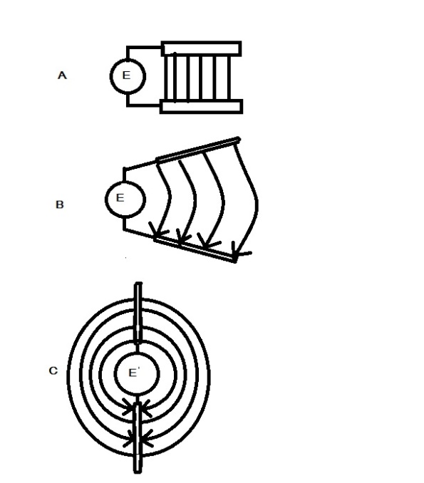
Fig.2 Electrical field between wires at various angles.
Assume that the sphere marked E in Fig.2C is a transmitter supplying RF energy. The two wires then can serve as the antenna for the transmitter. RF energy is radiated from the antenna and charges move back and forth along the wires, alternately compressing and expanding the flux lines of the electric field. The reversals in polarity of the transmitter signal also reverse the direction of the electric field.
When a charge is put on the plates of a capacitor by means of a battery (DC), an electric field is set up between its plates. The flow of charge from the source to the capacitor ceases when the capacitor is fully charged and the capacitor is said to be charged to a voltage equal and of opposite polarity to the source. The charged capacitor can be used as a source of emf since it stores energy in the form of an electric field. This is the same as saying that an electric field indicates voltage. The presence of an electric field around an antenna also indicates voltage. Since the polarity and the amount of charge depend on the nature of the transmitter output, the antenna voltage also depends on the energy source. For example, if a battery constitutes the source, the antenna charges to a voltage equal and opposite to that of the battery. If RF energy is supplied to a half wave antenna, the voltage across the antenna lags the current by 90 degrees. The half wave antenna acts as if it was a capacitor and it can be described as being capacitive.
Current and Magnetic Field
A moving charge along a conductor constitutes a current and produces a magnetic field around the conductor. therefore, the flow of charge along an antenna also will be accompanied by a magnetic field. The intensity of this field is directly proportional to the flow of charge. When the antenna is uncharged, the current flow is maximum, since there is no opposing electric field. Because of this current flow, a charge accumulates on the antenna, and an electric field builds up in increasing opposition to the emf of the source. The current flow decreases and when the antenna is fully charged, the current no longer flows
The magnetic field in the space around a current-carrying device has a specific configuration, with the flux lines drawn to a definite rule. Whereas in an electric field, the electric lines are drawn from a positive to negative charge, in the magnetic field the flux lines are drawn according to the left hand rule. The direction of current flow is upwards along both halves of the antenna. The lines of magnetic flux form concentric rings that are perpendicular to the direction of current flow. If the thumb of the left hand is extended in the direction of current flow and the fingers clenched, then the rough circles formed by the fingers indicate the direction of the magnetic field. this is the left hand rule, or convention, which id used to determine the direction of the magnetic field.
Combined Electric and Magnetic Fields
When RF energy from a transmitter is supplied to an antenna, the effects of charge, voltage and current, and the electric and magnetic fields are taking place simultaneously. These affects (Fig.3) have definite time and space relationships to each other. If a half wave antenna is used, the relations between charge and current flow can be predicted, because of the capacitive nature of the antenna. The voltage will lag the current by 90 degrees, and the electric and magnetic fields will be 90 degrees out of phase. With no electric field present (no charge), the current flow is unimpeded and the magnetic field is maximum. As charge accumulates on the antenna, the electric field builds up in opposition to the current flow and the magnetic field decreases in intensity. When the electric field reaches its maximum strength, the magnetic field ha decayed to zero.
A reversal of polarity of the source, reverses the direction of current flow as well as the polarity of the magnetic field, and the electrical field aids the flow of current by discharging. The magnetic field builds up to a maximum , and the electric field disappears as the charge is dissipated. The following half cycle is a repetition of the first half cycle but in the reverse direction. This process continues as long as energy is supplied to the antenna. The fluctuating electric and magnetic fields combine to form the induction field, in which the electric and magnetic flux maximum intensities occur at 90 degrees apart in time, or in time quadrature. Physically, they occur at right angles to each other, or in space quadrature. To sum up, the electric and magnetic fields about the antenna are in space and time quadrature.
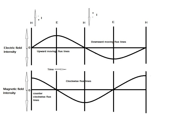
Fig.3 Electric and magnetic fields 90 degrees out of phase.
Part 2 will follow next week.
Making Waves -Slow Scan TV
One of the good things about the amateur radio hobby is its diversity. If you begin to become bored with one particular activity there are always plenty of other things to try. And so I decided to try something completely new (for me anyway) – HF Slow Scan Television or SSTV for short.
I downloaded the mmsstv software from http://hamsoft.ca/ and read through the instructions on setting up. All very simple really, much like setting up JT65, RTTY or any other soundcard based system/software. It does come with a few standard templates so I used these for a while until I got my head round the file size and clipping tools to create my own.
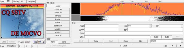 fig 1. My transmitted SSTV CQ message and control panel.
I have now made several contacts around Europe and Russia and the variety of images received is quite amazing. Contrary to popular belief, they are not pictures of nakedness – they are images of nature, wildlife or screen grabs from cartoons.
 fig2. Image received at M0CVO from SP5SMY.
Repairs and operations…. M0CVO Radio Blog 24/01/2016
This last week turned out to be an interesting one. On the 18th (Monday) I was given an old defunct radio – an IC-245. It is in fact a 2m multimode offering FM, USB and CW and was one of ICOM’s first CMOS controlled radios boasting two VFOs and PLL tuning. It was also the US version giving me a full 4MHz from 144 – 148MHz. It looked to be in reasonable condition for a 39 year old set (last made in 1976). However, it didn’t work. The screws holding the case together were missing and on opening up I noticed that some wires had been snipped – perhaps it had been an attempt at doing a mod to add LSB or similar that had gone wrong. Anyway, I repaired the wires but still nothing. I contacted ICOM UK Ltd and they sent me a new MOLEX type connector for the DC input – this was also missing which arrived the next day. Tracing the line back from DC in I noted that a small diode was “fused” (well, burnt out). I suppose the radio must have been connected up the wrong way round at some stage or fed with too high a voltage. Anyway, I checked in my junk box and found a small signal diode to replace the one that was crisped and tried again. Presto! we have power. Unfortunately though, no audio. Anyway, I plugged a headset in at the back and audio was produced here so the audio drivers were obviously functioning. I checked the external speaker/headphone socket but this was functioning correctly and switching back on to internal when the headphones were removed so I then checked the internal speaker. lo and behold one of the wires through the cone was broken. Anyway, I replaced the speaker with another and audio was heard. On TX a full 10W was transmitted and the TX audio could be heard in a second radio so all fine. So now I have both the FT-480R from Yaesu as a 2m multimode (30W) and an IC-245 from ICOM as a 2m Multimode (10W) but with the advantage of also covering the 146 – 148MHz portion of the band.
 Inside the IC-245 showing the FM board
 Inside the IC-245 underside showing the add on SSB board.
 replacement speaker
  Operational
So what else of my week? Well although I have been rather busy this week with work I have also found some time to get on the air and was lucky enough to find an opening on 15m yesterday that enabled me to get LZ1012SGM into the log and earn 10 points towards a diploma. I also managed to get Z62FB (Kosovo), 3Z90LKK (Polish club celebrating 90 years and offering points towards diploma) and Z63MES (Kosovo). This morning I noted that there was a CW contest so I gave away a few points to some Russian stations on 20m.
